
Shortly after assembly however, I noticed the case was not properly grounded. I think this was on my mind, as my recent reflow oven retrofit had this exact same problem. And that's a commercial product by a much larger company!
I mentioned this over on the Envox Discord Channel; I started the discord discussion on this topic in the #eez-bb3 channel, but it was suggested that I move it to the #crowdsupply channel. So the discussion continues there.
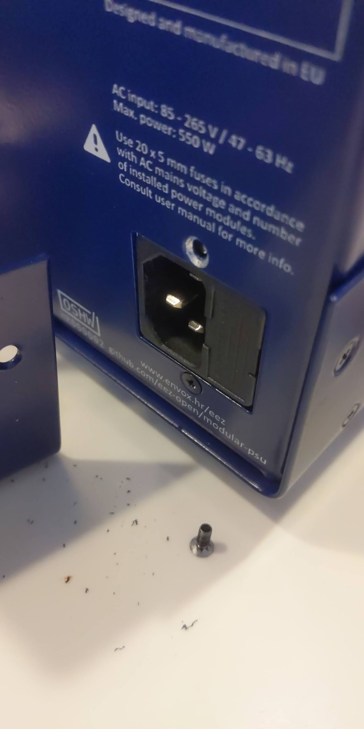
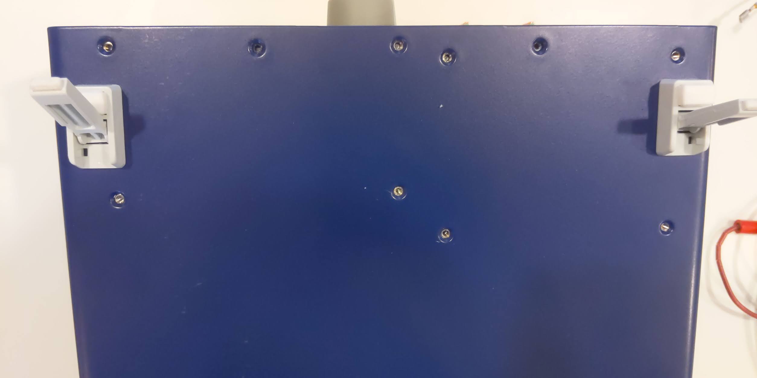
Sure enough: although there was an excellent paint job on the enclosure, there was not supposed to be paint where the standoffs meet the case:
"The fact is that one of the AUX-PS stand-off has connection to PE but enclosure maker didn't leave a part of bottom plate unpainted to make electrical contact" --prasimix (eez admin)
My initial solution was to scrape off the paint on the inside bevel of the screw holes. Done carefully, and there will be minimal to no visibility once the screws are re-inserted:

Note the screws are black (painted!) so for a good electrical contact, the undersides of the screws should *also* be scraped.
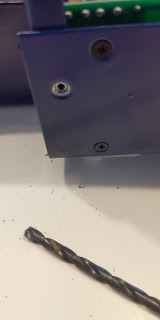
Initially I used a hand-turned, over-sized drill bit to scratch off the paint in the holes:


Really on the back and bottom, I think plain silver, unpainted screws would be best, however I don't have any on hand. Even on the sides this might be a good idea, although admittedly the black screws on the nice blue case is quite aesthetically impressive. Still, safety should always take priority.
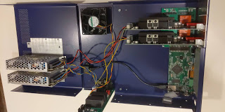
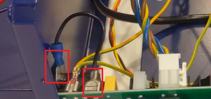
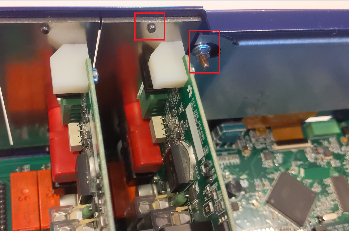
My next modification was to actually hardwire the ground connection to the case. Fortunately there's even a space lug awaiting the connector. Here the blue end is on the screw holding the power connecting to the case (also scraped off paint on case, see above) and the bare connector is attached to the extra lug on the auxiliary power supply:
Although my initial solution worked, it was admittedly lazy. The right way to do this would have been during assembly, to clean up all the paint around all of the standoffs. But I didn't really want to completely disassemble everything just to do this.
I started with just the removal of the cover, and the side screws holding the auxiliary power supply:

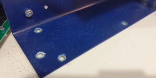
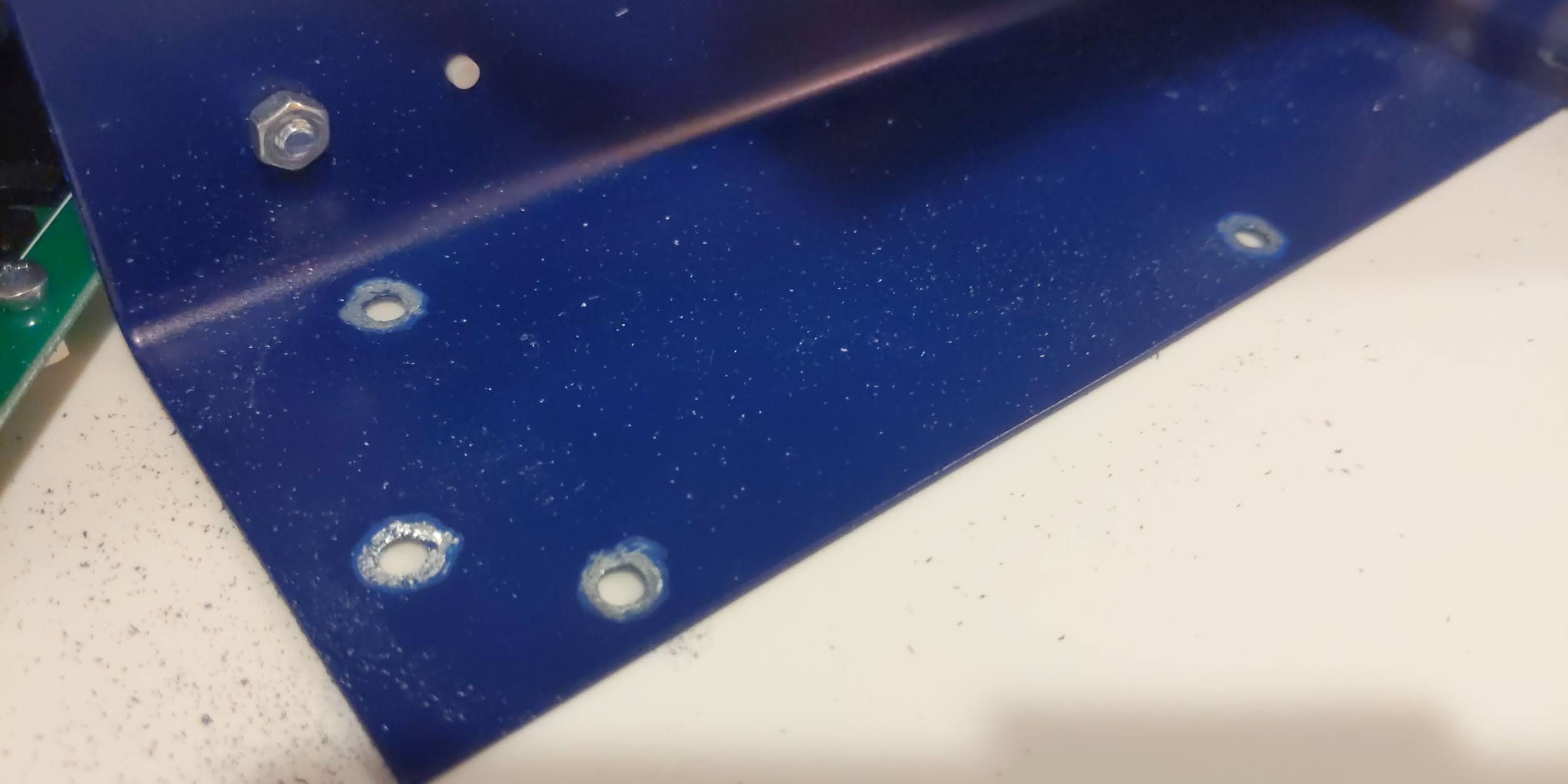
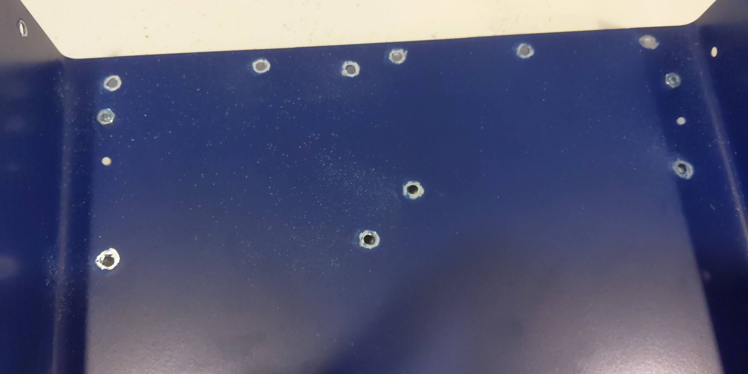
I then scraped off the paint in a little perimeter around the holes to ensure the standoffs would make electrical contact:
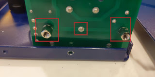
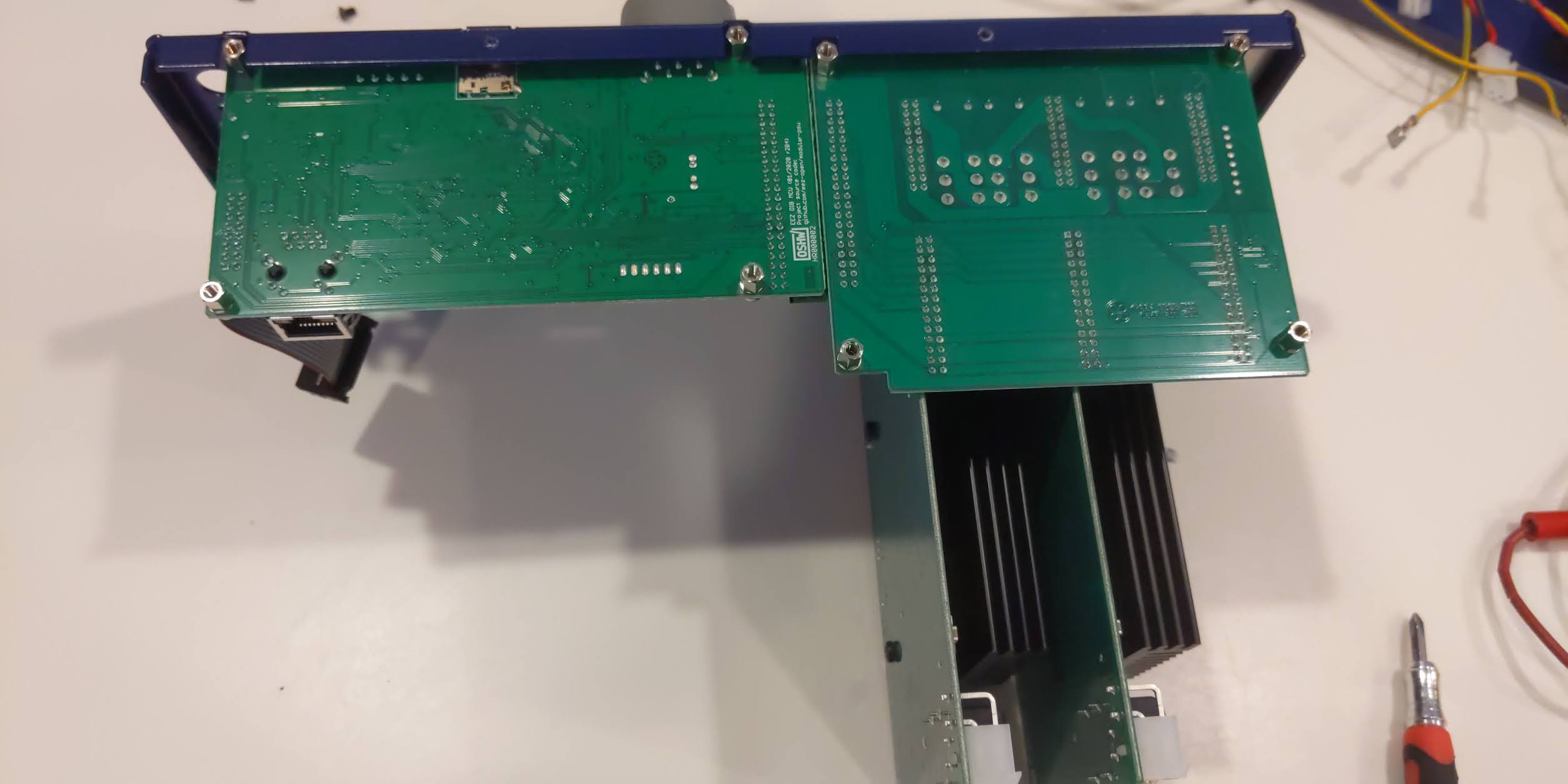
The two holes closest to the rear of the unit (near the power cable) have standoffs that are in direct contact with the incoming earth ground on the power supply connector mounted on the PCB, so it would probably be a good idea to ensure these are in good contact with the case.
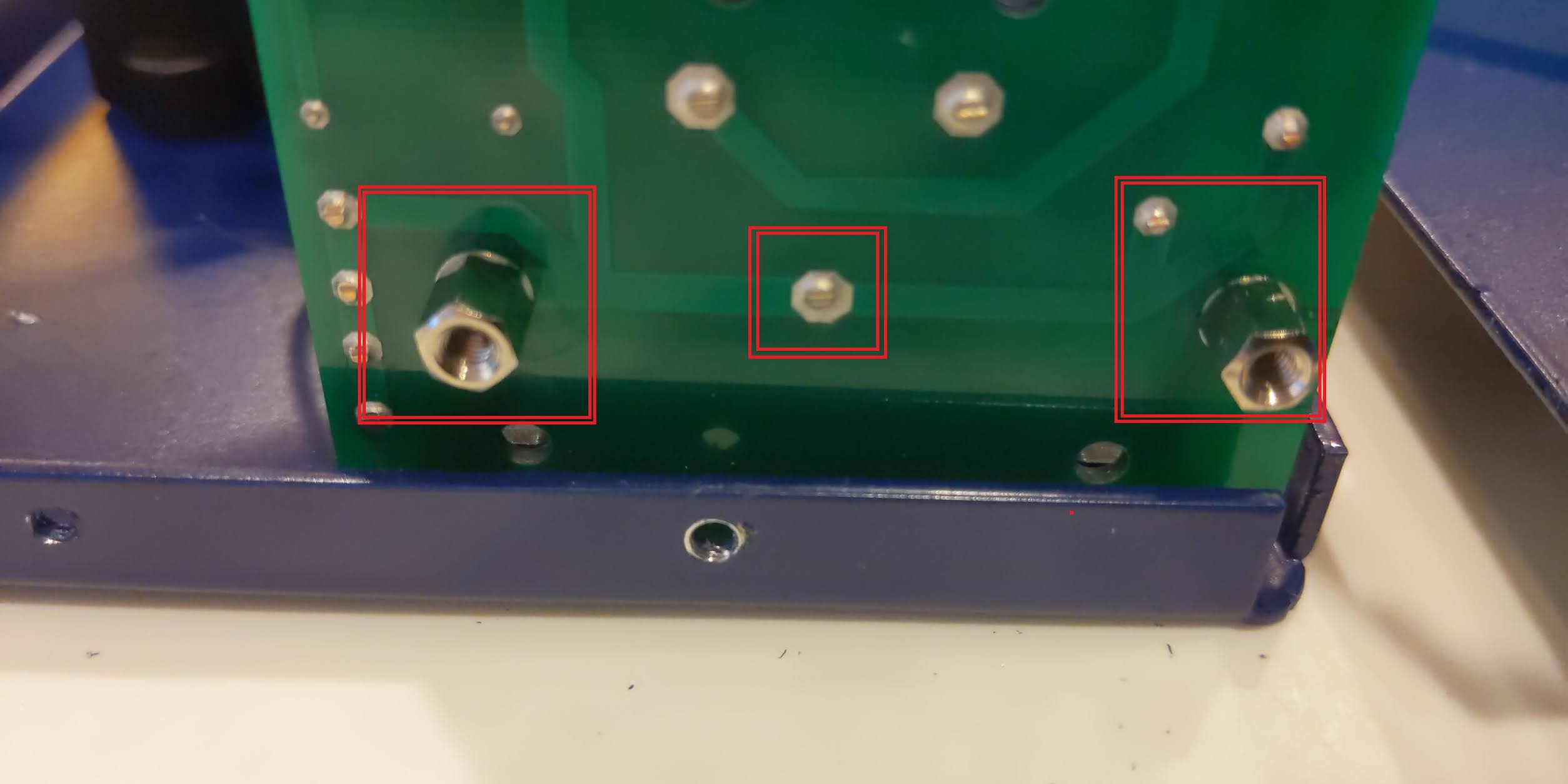
The red square to the left is the most important This one is closest to the inbound ground from the power connector (the ground pin in the small red square in the middle). Note the PCB trace. The connector to the right is not connected to anything.
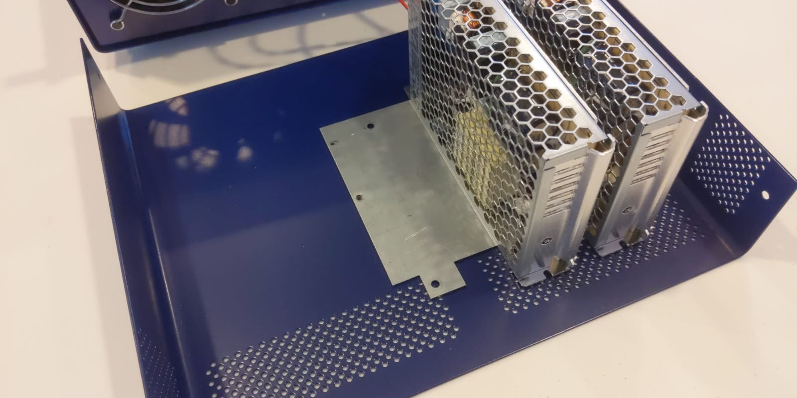
I ended up removing all of the screws from the bottom case:
This allowed removing the bottom cover, without having to disassemble the entire front panel, display, PCBs, etc:
The paint is fairly durable, some sandpaper on the end of a pencil or small nut driver might work. I used a Dremel tool on lowest speed setting to gently clean off the paint around all of the standoff connectors in the bottom panel:
Note the two screws that connect the front panel two the base should also conduct. Pay extra attention to these to ensure the best contact. It is really quite surprising just how well the painted case acts as an insulator. But with quality paint, and even painted screws - that's exactly what happens. Even upon assembly, the screws do not scratch the paint enough to make an electrical connection.
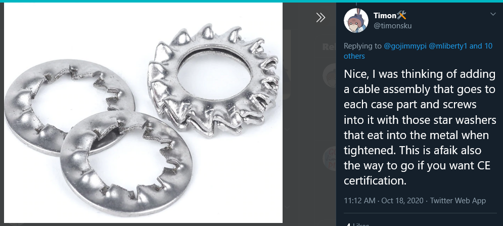
Edit: it's really great when a lot of people participate! All sorts of great ideas come about. @timonsku has an excellent suggestion of using those toothed lock washers to help make contact!
When re-assembling, but sure to connect the wires FIRST, before moving everything into place. Otherwise it will be difficult to reattach them. (yes, I learned this the hard way and removed all the screws in the auxiliary power supply a second time)

Afterwards, simply replace the bottom plate.
Really what I need to do is order some longer screws, and connect the front panel to case ground with wires, and not rely only on the (painted) screws to make a good electrical contact. Note the screws holding the display plate are apparently built-in to the case (my unit arrived with the display already mounted, and the screws to not come through to the front panel). This would be an excellent place for a wired ground connection:
When reassembling, be sure to check to top lid as well. Mine is completely insulated from the power supplies (not good).
Really, I think this is the best suggestion: to have welded posts on all 4 case parts. Thanks [timonsku] :

Hopefully the EEZ folks will mention this early on in their assembly instructions, as this whole process would certainly be easier before the unit is assembled.
Copyright (c) gojimmypi all rights reserved. Blogger Image Move Cleaned: 5/3/2021 1:35:54 PM