This is a continuation of my prior blog on limit switch mounting hardware design for the CNC3018.
There are plenty of resources on various limit switch wiring. As with most information on the internet: some is good, some not so good. One place to start for the desktop CNC is the gnea/grbl wiki: Wiring Limit Switches.
One of the first things to note is the Woodpecker board is designed such the the default switches are expected to be NO (Normally Open, High); The limit is triggered by pulling the signal low (short to ground). This is unfortunate, as switches will typically fail in the open position. Worse: Perhaps they even become disconnected and stay apparently open during a limit-exceeded condition.
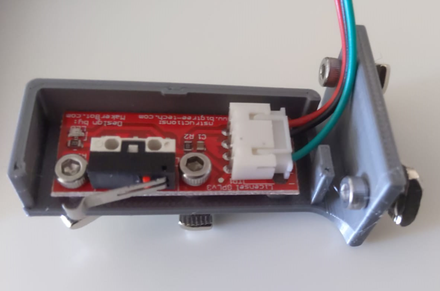
I ordered these switches from ebay. There are similar ones on Amazon. Here's a switch installed in the Y-Axis mount that I designed in Fusion360:
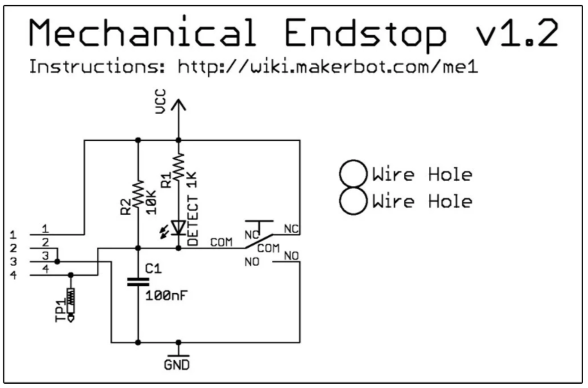
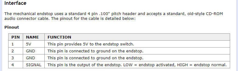
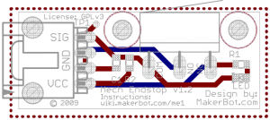
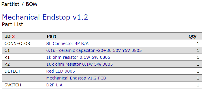
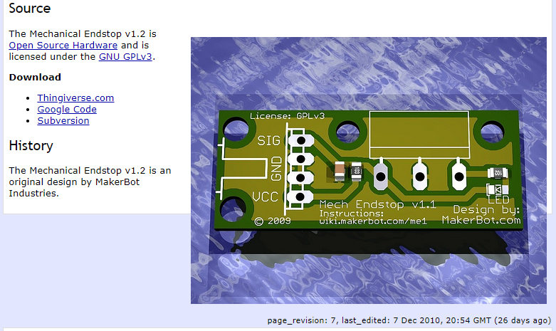
Although there's a wiki link on the board schematic, it has long since disappeared from the internet. Fortunately I was able to recover some key files from the wayback machine, and copied them here for reference (next 5 images credit: Makerbot):
Bill of materials:
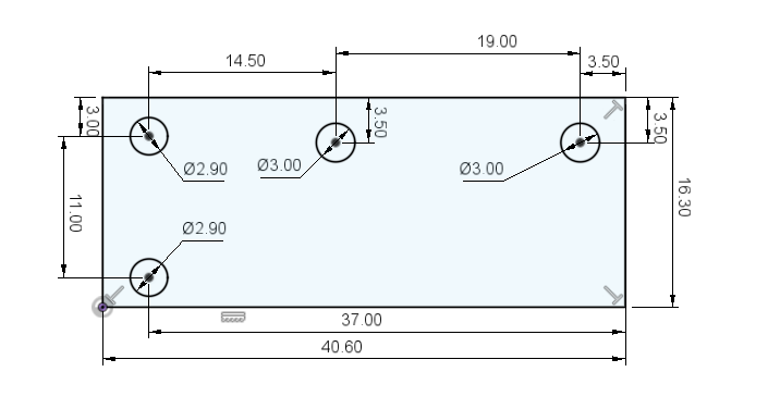
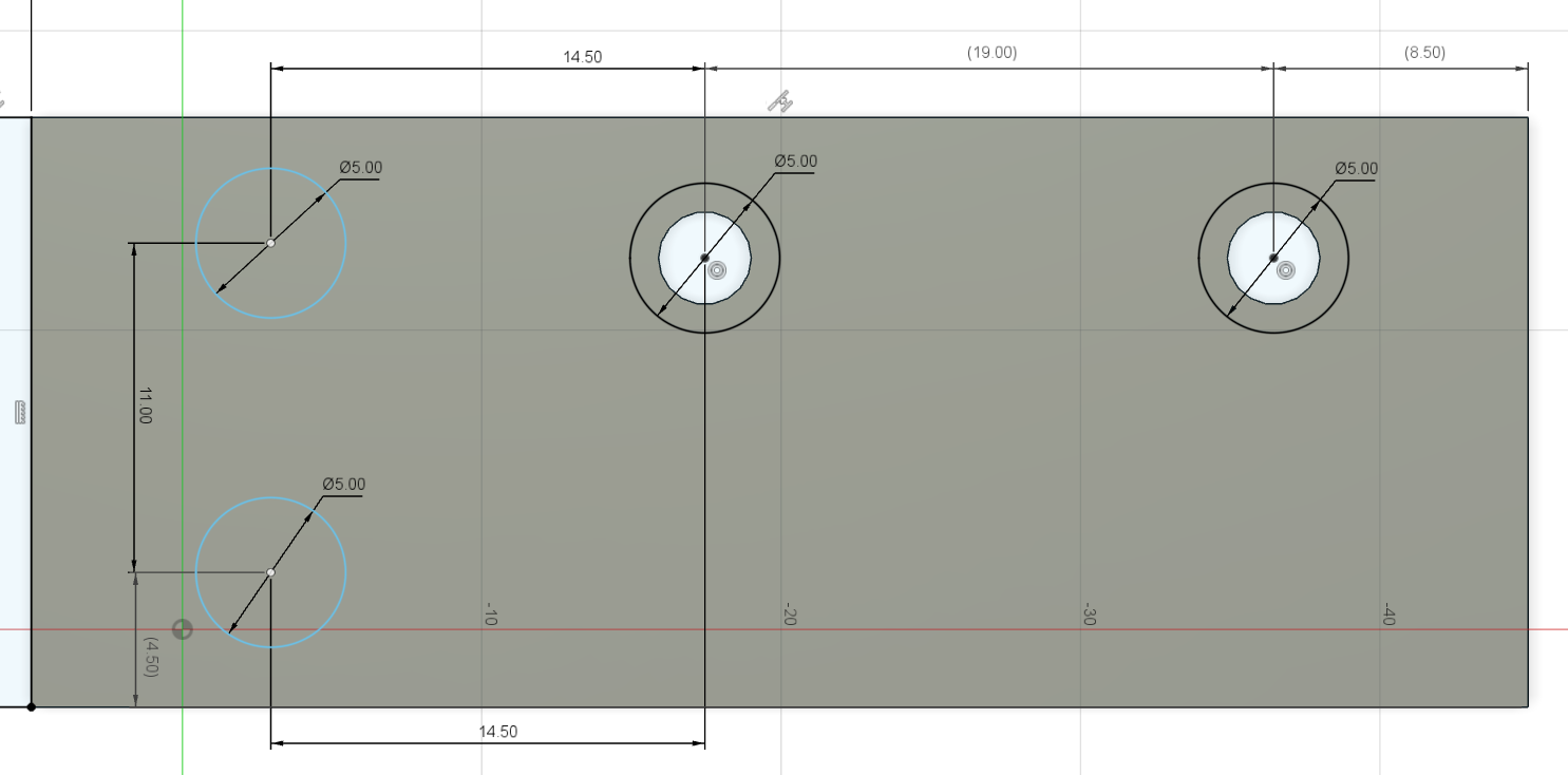
I needed to measure and create my own mechanical drawing with dimensions:
See the EccentricWorkShop schematic:
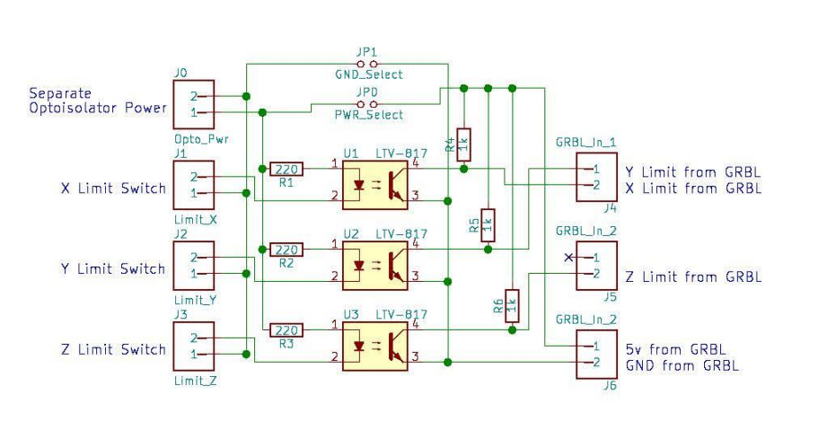
At one point, I thought I might need two of these isolator boards, as there is a connection for only 1 wire for each axis. However when looking at the schematic, it appears the limit switch detection is also tied together on the PCB:
So it appears that when limits are detected, there's no way for the software to determine which limit switch was triggered for a given axis. Although the software would of course know which direction it last send a g-code, so perhaps it could be inferred. Still, if there was a malfunction, it might be nice to know which switch actually triggered.
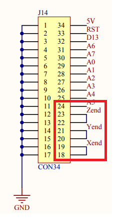
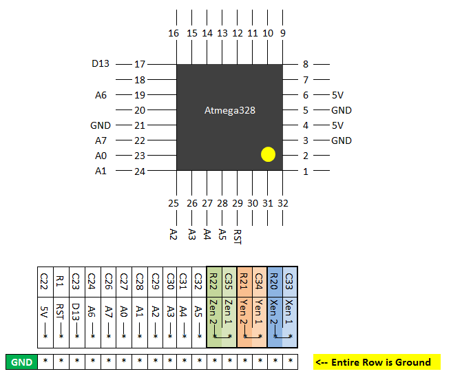
2* Limit-X-Axis2* Limit-Y-Axis2* Limit-Z-AxisA5 = ProbeA4 =A3 = Coolant EnableA2 = Cycle Start/ResumeA1 = Feed HoldA0 = Reset/AboutA7 =A6 =D13 = Spindle DirectionRST5V
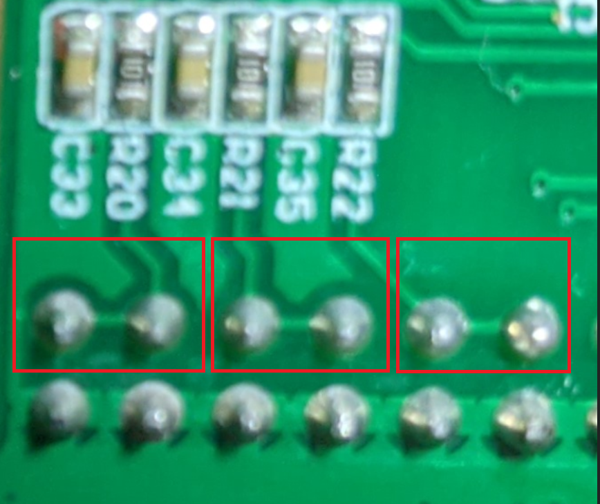
X = D9 = PB1 = pin 13 via R20Y = D10 = PB2 = pin 14 via R21Z = D12 = PB4 = pin 16 via R22

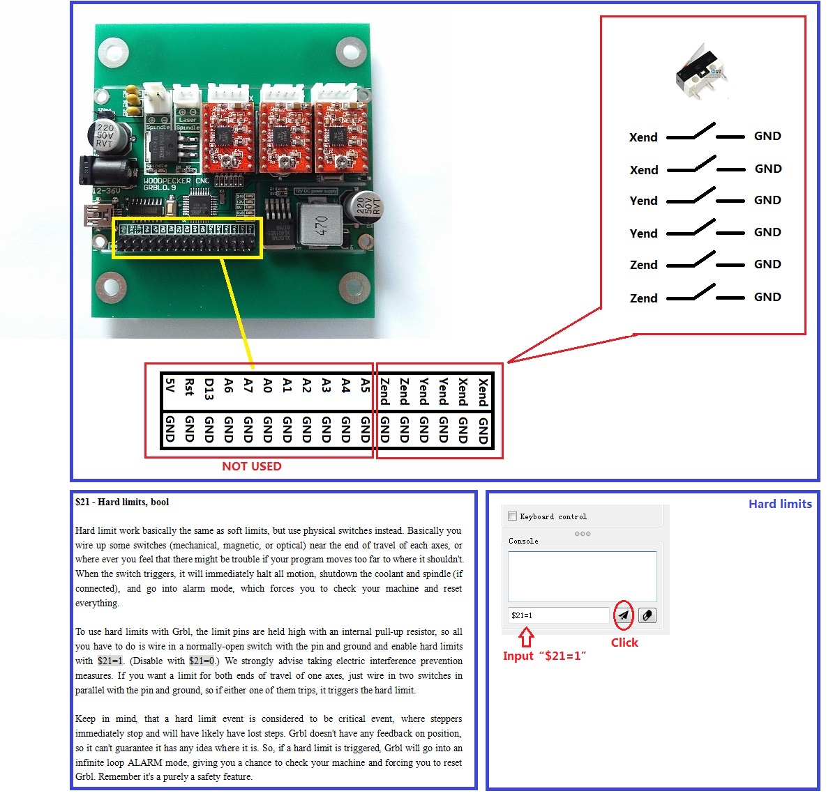
Reading the fine print in the text block, we see that hard limits are enabled with $21=1 ( of course they are). My $21 was found to be set to zero. Manually setting this to a value of 1 and tada! Upon pressing the limit switch while even manually moving the axis with the external controller, and the motion immediately stopped! See also the grbl documentation wiki.
The machine stop working randomly with the spindle still running
"This can be done by sending Control-X followed by $X"
-
linksprite wiki: DIY CNC 3 Axis Engraver Machine PCB Milling Wood Carving Router Kit Arduino Grbl
-
gnea/grbl Stock Controller Card Connecting Limit Switches #123
-
Denvi/Candle
Copyright (c) gojimmypi all rights reserved. Blogger Image Move Cleaned: 5/3/2021 1:35:54 PM