(work in progress, come back soon)
TL;DR
- The Diamond Lattice software is complex, difficult to use, and underwhelming.
- The FTDI drivers are (as usual) dreadful to deal with.
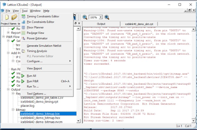
- Develop with iCEcube2; binary ends up in {project}_Implmnt\sbt\outputs\bitmap
- Program with Standalone 3.10 64-bit for Windows programmer.
- Sample code: https://github.com/gojimmypi/iCE40UP5k-blink (bin file here)
I initially tried to order the board from DigiKey. I gave up fussing with their dreadful ordering UI/UX and instead I ordered it from Mouser. (specifically this iCE40UP5K-B-EVN item on the Mouser web site). The device arrived about a week later.
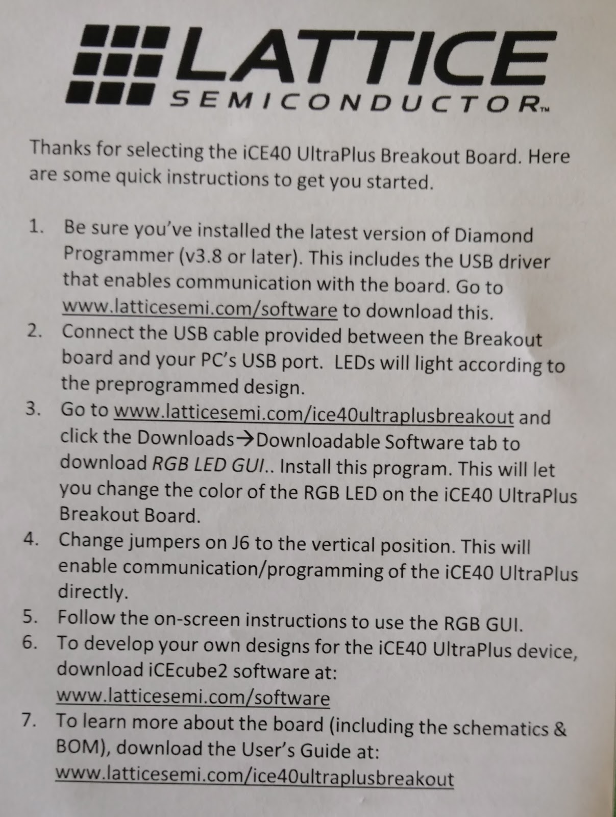
There was a (clearly hand-cut) quarter sheet of paper with instructions included with the board:
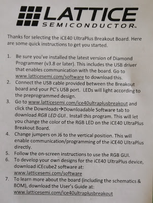
Mainly of interest are the links:
http://www.latticesemi.com/ice40ultraplusbreakout
and
http://www.latticesemi.com/software
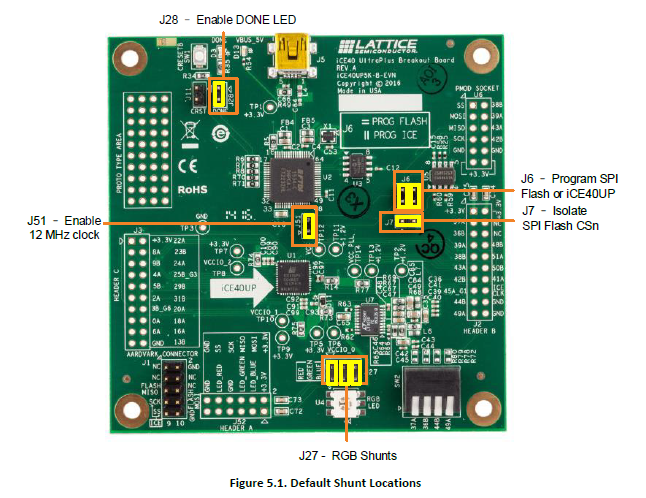
.. and the reminder to put the jumpers on J6 in the "vertical position" (perpendicular to the jumper at J7)
Despite the seemingly simply instructions, my initial out of the box experience was dreadful. Not only was the computer completely unable to connect to the board for the demo, but later once I was able to connect without the error, the demo didn't even work. I don't think my board shipped with the demo program installed, nor was I able to find the source code anywhere to try it.
Mainly of interest are the links:
http://www.latticesemi.com/ice40ultraplusbreakout
and
http://www.latticesemi.com/software
.. and the reminder to put the jumpers on J6 in the "vertical position" (perpendicular to the jumper at J7)
Despite the seemingly simply instructions, my initial out of the box experience was dreadful. Not only was the computer completely unable to connect to the board for the demo, but later once I was able to connect without the error, the demo didn't even work. I don't think my board shipped with the demo program installed, nor was I able to find the source code anywhere to try it.
The first problem seems to have been the fact that I already had installed FTDI drivers for my ESP32 development some time ago (specifically the rather rare JESP32). This was apparent when *both* FTDI devices were listed at the bottom of device manager, and when looking at properties - both were configured as JTAG devices:
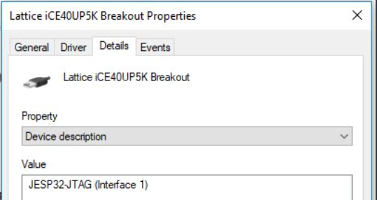
Looking back, I suppose this makes sense, as the JESP32 that was previously installed has the normal order of the devices reversed:
"Yeah. I used FT2232H interface 0 for UART and interface 1 for JTAG. This is different from many other debuggers. Advantages being you get same /dev/ttyUSB0 UART like many other dev boards. Also (which I heard) you don’t need to modify kext under OSX" - @ba0sh1
Sadly when the Lattice iCEcube2 software installs, it does not configure the ports properly. I ended up manually removing the drivers, then manually installing them. I'm pretty sure when I revisit my JESP32, it will not work.
I was unable to find any useful sample code for the iCE40UP5K. I eventually found this:
https://github.com/cliffordwolf/icestorm/tree/master/examples/up5k_rgb
I was unable to program from the Lattice iCEcube2 software, as there was no "Tool - Program" on my menu!
I needed to download the "Standalone Diamond Programmer" from here:
http://www.latticesemi.com/Products/DesignSoftwareAndIP/ProgrammingAndConfigurationSw/Programmer
Don't bother using the site search to find this! Seemingly every software item *except* the one you want will be listed in the hundreds of results. (yes, I mistakenly tried installing an older version, and the iCE40UP is not listed as a device). The version that worked for me was 3.10.0.111.2 (I manually installed this one, different than the one that came with Lattice Diamond install) Specifically this link:
Programmer Standalone 3.10 64-bit for Windows
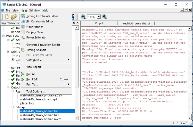
From the iCECube2 output, once a project is successfully compiled, the resulting file can be found in the log output near the end (see above). In my case, the bin file was found here:
C:/lscc/iCEcube2.2017.08/sbt_backend/Projects/blink/blink_Implmnt\sbt\outputs\bitmap
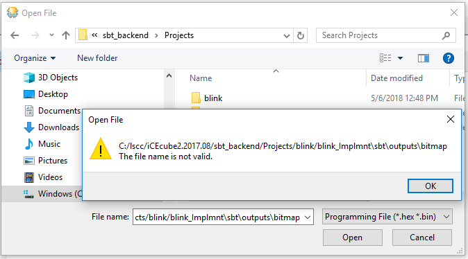
Note the annoying, sloppy use of forward and back slashes. They will need to be edited in Windows, otherwise an error occurs when pasting in the path.
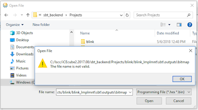
Windows only likes back-slashes, so each will need to be individually changed. In my case, the default project ended up in:
C:\lscc\iCEcube2.2017.08\sbt_backend\Projects\blink\blink_Implmnt\sbt\outputs\bitmap
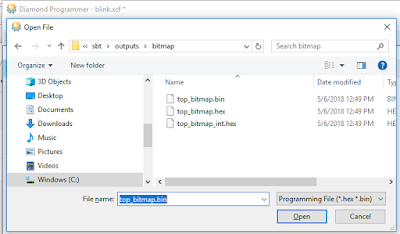
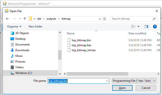
And the file needed (mysteriously) is prefixed with "top_". Select that bin file in the Diamond Programmer by clicking on the little 3 dot ellipsis button:
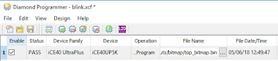
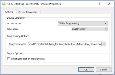
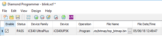
It should pop up a dialog box like this:
Note the device family is set to iCE40 Ultra Plus and the Device is iCE40UP5K.
Double-click on the "Operation" column (or click the "Device Properties" button) and ensure these settings are in place:
I saved my working project to GitHub here: https://github.com/gojimmypi/iCE40UP5k-blink
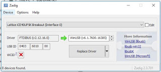
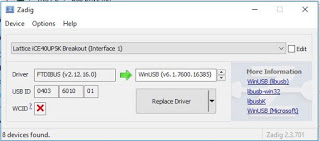
Once working, when viewing with Zadig , this is what I see (note Interface 0 and Interface 1):
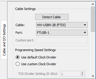
However programming is not always successful, even if the software finds the device:
If the programming fails like this, try switching ports. One one computer (one that I had not installed JESP32 FTDI drivers)... I was able to program on the default "Port 0" (FTUSB-0) - on another computer (the one I previously had configured FTDI drivers, I had to change to "Port 1" (FTUSB-1) in order to program.
In the end I was eventually successful , but I don't think the iCE40UP5K is for everyone.
I was unable to find any useful sample code for the iCE40UP5K. I eventually found this:
https://github.com/cliffordwolf/icestorm/tree/master/examples/up5k_rgb
I was unable to program from the Lattice iCEcube2 software, as there was no "Tool - Program" on my menu!
I needed to download the "Standalone Diamond Programmer" from here:
http://www.latticesemi.com/Products/DesignSoftwareAndIP/ProgrammingAndConfigurationSw/Programmer
Don't bother using the site search to find this! Seemingly every software item *except* the one you want will be listed in the hundreds of results. (yes, I mistakenly tried installing an older version, and the iCE40UP is not listed as a device). The version that worked for me was 3.10.0.111.2 (I manually installed this one, different than the one that came with Lattice Diamond install) Specifically this link:
Programmer Standalone 3.10 64-bit for Windows
From the iCECube2 output, once a project is successfully compiled, the resulting file can be found in the log output near the end (see above). In my case, the bin file was found here:
C:/lscc/iCEcube2.2017.08/sbt_backend/Projects/blink/blink_Implmnt\sbt\outputs\bitmap
Note the annoying, sloppy use of forward and back slashes. They will need to be edited in Windows, otherwise an error occurs when pasting in the path.
Windows only likes back-slashes, so each will need to be individually changed. In my case, the default project ended up in:
C:\lscc\iCEcube2.2017.08\sbt_backend\Projects\blink\blink_Implmnt\sbt\outputs\bitmap
And the file needed (mysteriously) is prefixed with "top_". Select that bin file in the Diamond Programmer by clicking on the little 3 dot ellipsis button:
It should pop up a dialog box like this:
Note the device family is set to iCE40 Ultra Plus and the Device is iCE40UP5K.
Double-click on the "Operation" column (or click the "Device Properties" button) and ensure these settings are in place:
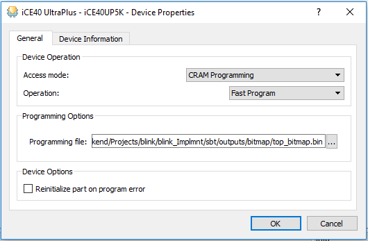
I saved my working project to GitHub here: https://github.com/gojimmypi/iCE40UP5k-blink
Once working, when viewing with Zadig , this is what I see (note Interface 0 and Interface 1):
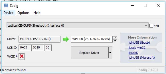
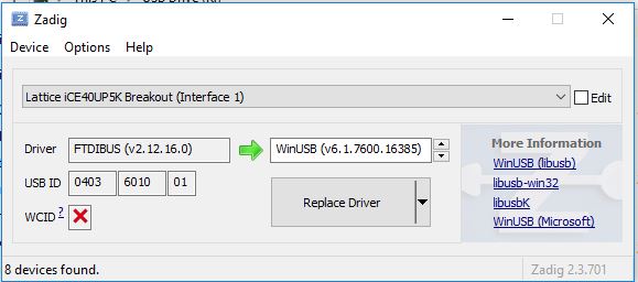
However programming is not always successful, even if the software finds the device:
INFO - Check XCF Project: The current XCF Project is valid.
INFO - Check XCF Project: The current XCF Project is valid.
INFO - Check configuration setup: Start.
INFO - Check configuration setup: Successful (Ignored JTAG Connection Checking).
INFO - Device1 iCE40UP5K: Fast Program
 "Device detection failed. Cannot continue."
ERROR - Process Operation Failed.
INFO - Elapsed time: 00 min : 00 sec
ERROR - Operation: unsuccessful.ERROR - Programming failed.
If the programming fails like this, try switching ports. One one computer (one that I had not installed JESP32 FTDI drivers)... I was able to program on the default "Port 0" (FTUSB-0) - on another computer (the one I previously had configured FTDI drivers, I had to change to "Port 1" (FTUSB-1) in order to program.

In the end I was eventually successful , but I don't think the iCE40UP5K is for everyone.
Copyright (c) gojimmypi all rights reserved. Blogger Image Move Cleaned: 5/3/2021 1:35:53 PM