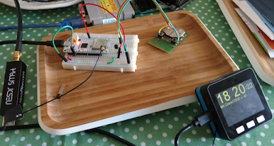
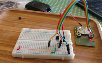
My plan is to use LoRa to communicate from an M5Stack console to a distant LoRa32u4 , each equipped with a LoRa module; essentially push the button of the remote from afar! The actual pysical button push on the M5Stack will essentially be "sent" (via LoRa message) to the remote 32u4 which will then trigger the actual remote control transmitter. The working prototype is shown here:
How to get there: The first thing needed is to disassemble the remote and determine how it normally works. The remote I am using is a Somfy TR2 similar to this one that can control two different devices. Upon disassembly, the first thing we see is those two buttons each with 4 pins. The buttons appear to be very similar to this Grayhill Gull Wing 95C06C3RAT at Mouser as documented here . Note that although there are 4 pins, it is simply a SPST switch:
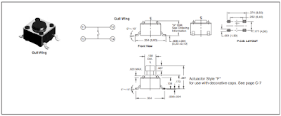 |
| Photo credit: Grayhill spec sheet |
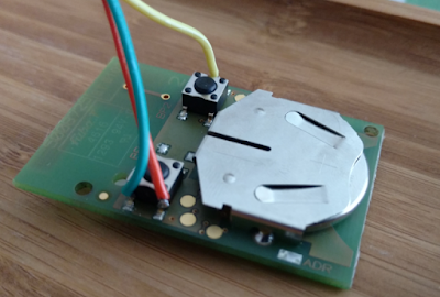
I confirmed both visually and with an ohmmeter that indeed I have a similar switch and proceeded to connect some external wires to it:
If you look closely, I took the time to wrap the wire around the pin of the switch to make a good mechanical connections, while being careful not to touch any other circuit. It would probably be a good idea to use some hot melt glue and affix the wires to the pc board.
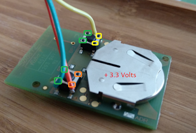
Here, Green is a ground (all 4 pins, 2 from each switch); Orange is BP1 and Yellow is BP2. The top of the battery is labeled as being the positive side. The entire metal surface here is at 3.3V:
This turned out to be an extremely handy arrangement for me: the entire device could essentially be the "load" for an NPN transistor circuit!
Putting an ammeter between either the orange or yellow pins to ground, I found about 0.3mA that would otherwise flow though the button (or a transistor).
Looking at the specs for the 2N3904, the max collector current is a whopping 200mA max, well over a couple orders of magnitude for what we'll need:
And for a collector current of (we'll round up) to 0.5 mA, we'll have a minimum gain of around 60 to 80 (let's pick a gain of 70 for discussion-sake):
We'll need a base current of around (0.005A / 70) = 0.0714 mA; For the current-limiting base resistor, we'll thus need: 3.3v / (0.0000714) ~= 40K ohms. I didn't have a 40K handy, but I did have a bunch of 20K ohm resistors laying around, so I'll use that. It is still well within spec, and will certainly account for any gain drift or degradation.
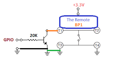
Our button-pressing supplement thus looks like this (shown for BP1, but the same for BP2):
Note that this circuit will allow our 32u4 to control the remote via a GPIO pin. Fortunately the remote is also smart enough to turn itself off - if for some reason the button remains pressed so that the battery does not drain (such as being poked by your keys in your pocket). In our case: regardless of the state of the pin during power up (or application crash) the battery will be preserved.
The manual prototype looks like this:
Note the red wire to drive the base of the transistor is stuffed into the battery holder for the picture. Once in operation this red wire will instead be the GPIO output from the 32u4.
Next, we need to make sure the remote is actually working! As mentioned in my previous blogs on M5Stack LoRa Range Issues as well as this fun project using OpenWRT on EA3500 with RTL-SDR Stream, I have an inexpensive NooElec SDR, that is simply amazing - particularly given the price! With this hardware, and the some software , we'll be able to "see" the remote signal.
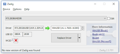
The last time I used Cubic SDR, it was working fine. Today? Nothing. Erg. Gotta love Windows. App starts, no complaints, but no signal. A little bit of googling, and there's the Quick Start Guide. First thing I noticed was mention of my old friend, zadig . Sure enough: during one of the the Windows updates, the default driver was changed for some bizarre reason. Here's the screen just before correcting it:
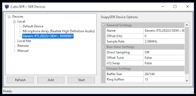
And tada! Exit Cubic SDR (no need, at least for me, to reboot computer)... relaunch Cubic SDR app... then pressing Start for my RTL2832U device:
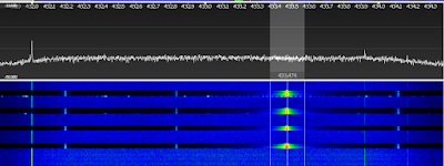
The waterfall immediately starts! Press the button on the remote a few times, and we can see the pulse at about 433.5 MHz. Notice the messy side-band noise, as well as someone else continuously transmitting at about 432 MHz:
I have the source code for all this on GitHub here: https://github.com/gojimmypi/LoRa-GPIO (note there are also Development and M5-RadioHead branches, but after a bunch of GitHub fussing, I think the master branch is now up to date). The projects are VisualMicro extensions to Visual Studio, but I suspect the Arduino code would work just fine in the Arduino IDE.
More to come...
Copyright (c) gojimmypi all rights reserved. Blogger Image Move Cleaned: 5/3/2021 1:35:53 PM


